Sierra West Machine Shop Build
We take a hiatus from the model railroad to check in on my progress of the build of the Sierra West Machine Shop for my friend, Doug Matheson. Below is an article I wrote for my local club, OVAR (Ottawa Valley Associated Railroaders) detailing some of the steps involved.
To enlarge the images, simply click on them.
To return to the default look of the page, click outside them.

Here are a few images I took outdoors showcasing my progress on the Sierra West Scale Models machine shop in O-scale.

The machines came from Sierra West, but I scratchbuilt the shop building.


This picture showcases my most recent progress. Three O-scale figures have been painted and weathered and are momentarily leaning up against a couple of machines. This is but a temporary placement for the photographer. These three lads could end up anywhere in the shop or on the diorama.
To see a detailed step-by-step clinic of this build with hundreds of images you can visit my Craftsman Structures blog at the following address. Simple copy and paste it into your computer's browser.
craftsmanstructures.blogspot.com
Below is a shorter version of the build with a limited number of images.

Retirement is glorious!
Following my 40 year teaching career I now find myself with the time
required to complete large modeling projects which had been started when I was
still in front of a classroom of students. The image above showcases the machines in their place along the shop floor belted to the countershafts. A "mock" roof is momentarily in place.

One such project is the Machine Shop Diorama build I am working on for my good friend, Doug Matheson. A couple of years ago Doug approached me and asked if I would build the remaining machines from his Sierra West collection.
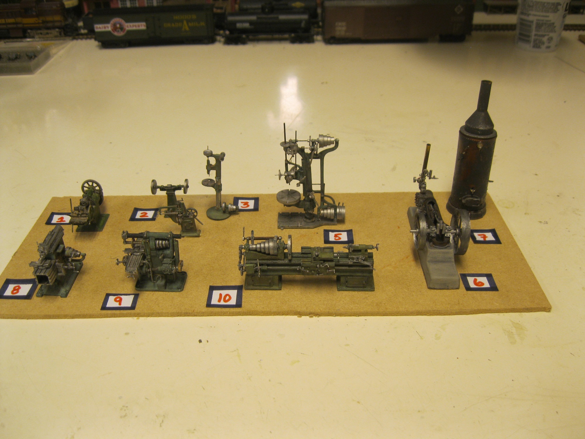
Doug had already finished two of the smaller machines as
well as the boiler. My task would be to build
the remaining six machines along with the machine shop engine before taking on
the building of the shop structure itself.

While the size is O-scale (1:48) these machines remain
small and packed with many detail items.
For example, the universal miller above is but a mere inch and a half tall yet
it contains some 40 smaller individual detail parts. The main body of the machine came in a few pieces as well and had to be constructed, painted and weathered.

To help “busy” up the scene, Doug had purchased a few
extraneous detail collections offered through Sierra West. The level and quality of these detail castings
is spectacular offering the modeler a great blank canvas for painting and
weathering with very little cleaning necessary.
I enjoyed “going to town” on these!

Doug drew up the scale plans on paper for the main building and I created the wall sections using the board and batten method out of basswood material. The walls were placed on a plywood base Doug created. I added scale flooring which I stained and weathered with a combination of paint, stain and weathering powders. I used the same methods for the interior walls. Doug's favourite colour was chosen for the exterior wall, Prussion blue. I applied the paint in a series of washes before weathering. Grandt Line windows were coloured off-white. The window presented a problem as they would be seen from both sides. I would have to paint the opposite (interior) sides and add glass between all smaller window segments. I thank my longtime friend, Bill Meek, for lending me a bottle of Micro Kristal Klear, as I had none at my workbench...and we were in the midst of Covid times with stores shut. He had met with success with this product in HO scale. I was concerned that I wouldn't be able to "spread" the clear material across the larger openings in O-scale, but my fears never materialized. The product worked beautifully. Doug tells me the stone foundation comes from a company in Greece, of all places! Cut to size, it looks totally realistic viewed from very close up. Once the walls were erected and the office area created, I focused on creating the rafters, of which there are nine in total. They must match the configuration of the upper area of the two end walls. Seeing as I would have to remove the rafters to offer arm access while creating the interior of the shop I added a tiny dab of glue to hold them in placed momentarily for the photo to offer me an indication of how they would look at the time.

Pleased with the result, they were taken down. I then determined the exact location of all
the machines on the floor of the shop taking care to “visualize” where the
belts from the machines would reach up to the countershafts. Seeing as a belt could not reach up beneath a
rafter beam, some “trial and error” positioning attempts would have to be
made. I then drew a floorplan noting
machine locations and placed the rafters atop the plan allowing me to determine
the exact location of all of the bearings and respective pulleys for the shafts
and the countershafts. The main (or
central) drive shaft was centred between countershafts on either side.

Following the addition of miscellaneous benches, tables
and shelves I built the shop heater as it came from a kit. I painted it black
and weathered it with rust coloured powders.
I then extended its pipe up to where it would meet the roof and built
from scratch a small box to hold firewood.

The next procedure was the painting, weathering and positioning
of the hearth. I built a small coal
storage area from scratch and placed it nearby against the far wall. Next up were the support posts for the rafter
footings. To each post I added a lantern
carefully hiding its wiring in a recessed area along the back of the post. The lanterns came from Gilbert Lacroix (GLX
Scale Models Inc.). Joining the shop
engine to the boiler with metal piping proved rather difficult. I had to bring the two models out from the
shop floor and carefully determine the distance between them. Some of the piping also exited out the side
of the building. Once the two objects
were carefully joined I took “surgeon’s care” in moving the conjoined units
back onto the shop floor in the hope the piping would “hold” and it did,
thankfully! The shop engine became the
first item joined by a belt up to the main drive shaft in the rafters.

I removed the upper rafter sections from their footings
as the process of glueing the machines in place, one at a time, began. I again referenced the drawing I had made to
determine the proper location of each machine on the shop floor before
attaching a belt from the pulley on the machine up to its’ appointed countershaft. The countershaft for each machine was created
on the workbench as a full assembly and then placed up top the rafter
beam. As for the belting, I pondered for
a while the material to use that could be painted and not warp over time due to
climate and moisture conditions. Doug
had read about Tyvek and we decided to give it a go. It worked perfectly! I painted the belts a burnt sienna colour and
later weathered them down. They match
the colours perfectly from many images of belts I found on-line. Following the shop engine, the first machine
to go in place was the 36” vertical drill.
Because it has a belt shifter on its lower pulley, it was not necessary
for me to create a shifter up top. Initially, I had inadvertently placed a third pulley on the countershaft up top, but because Doug and I realized it was not required I removed it as you can see in the next image where only two pulleys properly reside on the countershaft to the right.

The next machine on the list was the 24” engine
lathe. It would require a belt shifter
up in the rafters to move the belts to the various sized pulleys down
below. This meant the creation from
scratch of the countershaft along with the planking to allow the wooden belt
shifter to be swung along its fulcrum to move the belts. I took care to determine the proper distances
for the bearings to hold the assembly. Tiny
detail parts were glued along the smaller rod attached to the belt shifter that
would act as guides to move the belts. (Image 9)
I scratchbuilt each wooden paddle that acts as the belt shifter. It typically tapers down to a narrow handle
at the base which is painted red for safety.

Should the operator wish to engage (or
disengage) the machine, he simply “bats” the wooden belt shifter with his
gloved hand and it moves the belt up top, starting the machine spinning or
stopping it from spinning. (On each
countershaft there are three pulleys, one attached to the main drive shaft with
one attached to the machine below located beside another pulley that spins free
of the shaft, the one that would essentially turn the machine off.) Should
the operator wish to change the speed of the machine he simply moves the belt
to the left or right of the cone pulley attached to the machine itself. (Some of the smaller machines only operate at
the fixed speed of the main drive shaft and do not contain cone pulleys.)
With all of the machines
in place it was time to create the venting for the blacksmith’s hearth
including the hood above the hearth. The
vent would lead up through the roof.
Since there was no kit, I scratchbuilt the entire assembly from
styrene. (I first created a mock-up from
cardboard.)
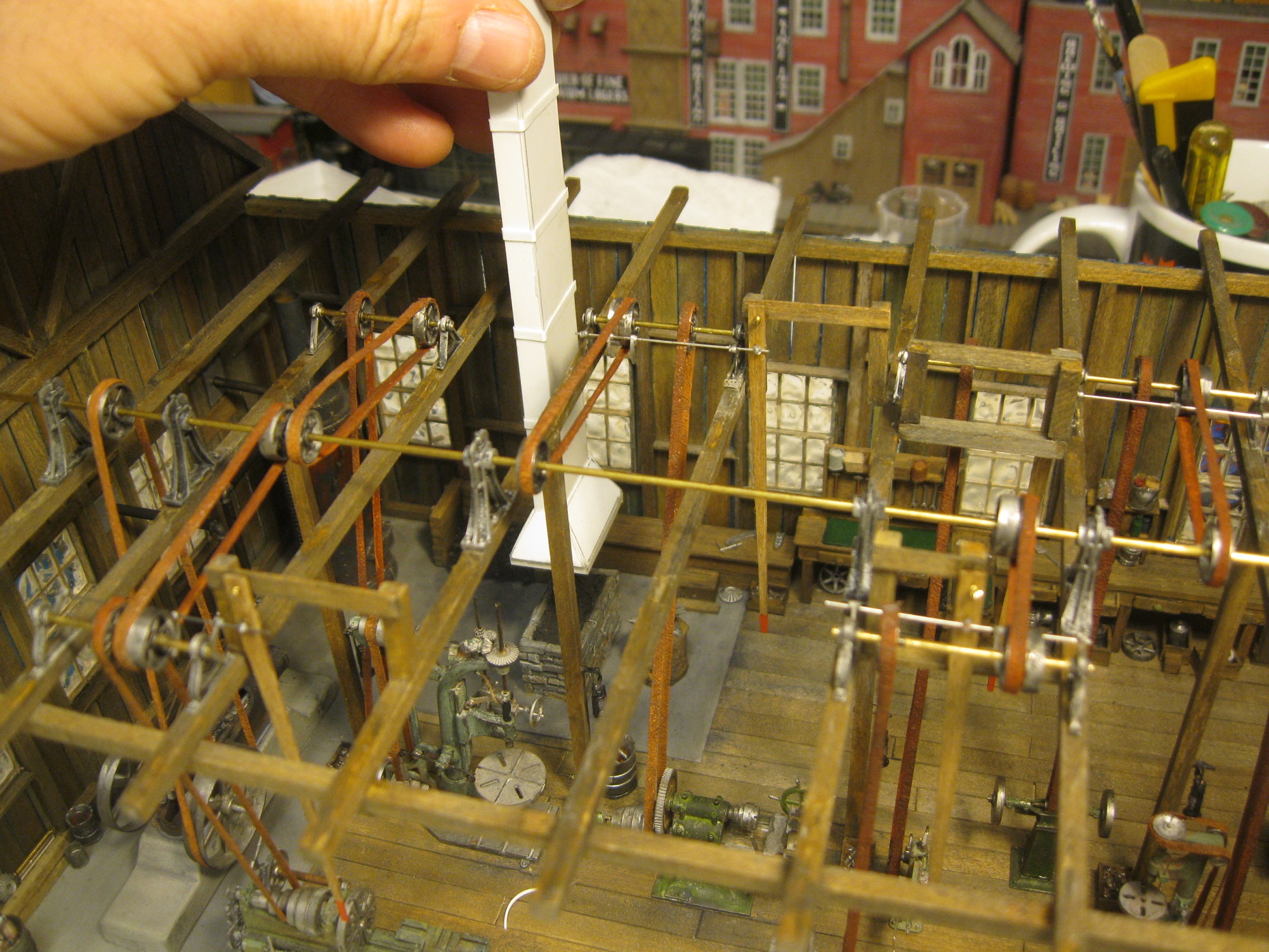
I shaped the vent hood in a rectangular fashion in order
to match the shape of the hearth, then painted and weathered it.

In order to remain in place, I glued a couple of supports up in the rafters between the rafter beams. Since the roof will be removeable I chose to truncate the top of the vent just below the roof. It's extension up top of the roof will be glued directly to the roof itself. (I used this same strategy for the piping leading up through the roof for the shop heater.)
There remains a great deal of work yet to be done on the machine shop. I have taken images indoors with incandescent lighting.
as well as
outdoors on a sunny day with my old “point and shoot” camera to share with Doug during these pandemic times. Doug recently asked me how many hours I had
put into the project and he mused, “Two hundred, three hundred?” I’m not really sure how many hours have been
spent at the workbench but I am certain of one thing. It is pure joy working on a project with a theme
I had been totally unfamiliar with as it has been a tremendous learning
experience for me!

As a tandem of Bluebirds head outbound from North Dover, destination...Portland, Maine, I wish to take this time to say, "Thank you for checking in on my latest project!"
Mike Hamer, Ottawa, Ontario, Canada


